BNK Set - Mini Preloaded
Finished Shaft Ends
To meet the space-saving requirement, this type of Ball Screw has a standardized screw shaft and a ball
screw nut. The ends of the screw shaft are standardized to fit the corresponding support unit.
Downloads - Log In required
Hide Filters
Show Filters
Shopping Options
Please Log-in to see pricing, CAD Models and Catalogs
Don't have an account? Sign up here.
In stock
Related Products


-
Ball screw specification Screw shaft diameter (mm) 4 Lead (mm) 1 BCD (mm) 4.15 Thread minor diameter (mm) 3.4 Number of circuits 3×1 Axial clearance 0 Basic dynamic load rating Ca (kN) 0.29 Basic static load rating C0a (kN) 0.42 Preload torque (N-m) to 0.0098 Spacer ball None Rigidity (N/µm) 35 Circulation method Deflector Applicable fixed side support unit EK4, FK4 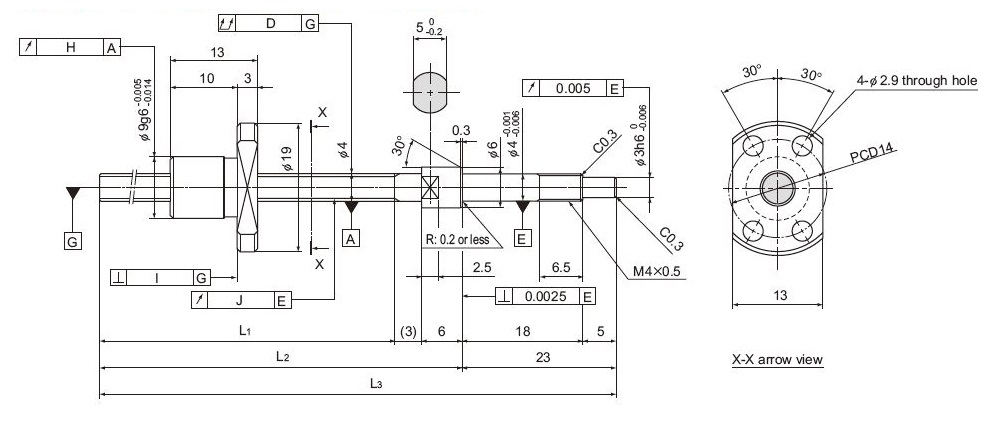
Model No. Stroke Screw shaft length Ball screw specifications Lead angle accuracy L1 L2 L3 Runout of the screw shaft axisD Runout of the nut circumferenceH Flange perpen-dicularityI Runout of the thread groove srufaceJ Representative travel distance error Fluctuation mm mm mm mm mm mm mm mm mm mm BNK0401‑3G0+77LC3Y 20 45 54 77 0.015 0.009 0.008 0.008 ±0.008 0.008 BNK0401‑3G0+77LC5Y 20 46 54 77 0.025 0.012 0.01 0.01 ±0.018 0.018 BNK0401‑3G0+97LC3Y 40 65 74 97 0.02 0.009 0.008 0.008 ±0.008 0.008 BNK0401‑3G0+97LC5Y 40 66 74 97 0.025 0.012 0.01 0.01 ±0.018 0.018 BNK0401‑3G0+127LC3Y 70 95 104 127 0.025 0.009 0.008 0.008 ±0.008 0.008 BNK0401‑3G0+127LC5Y 70 95 104 127 0.035 0.012 0.01 0.01 ±0.018 0.018 AFB-LF is the default grease. For more detailed specifications, please download the Product Catalog with the link in the Downloads section on this page. -
Ball screw specification Screw shaft diameter (mm) 5 Lead (mm) 1 BCD (mm) 5.15 Thread minor diameter (mm) 4.4 Number of circuits 3×1 Axial clearance 0 Basic dynamic load rating Ca (kN) 0.32 Basic static load rating C0a (kN) 0.55 Preload torque (N-m) to 0.0098 Spacer ball None Rigidity (N/µm) 47 Circulation method Deflector Applicable fixed side support unit EK4, FK4 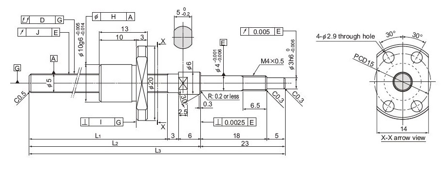
Model No. Stroke Screw shaft length Ball screw specifications Lead angle accuracy L1 L2 L3 Runout of the screw shaft axisD Runout of the nut circumferenceH Flange perpen-dicularityI Runout of the thread groove srufaceJ Representative travel distance error Fluctuation mm mm mm mm mm mm mm mm mm mm BNK0501‑3G0+77LC3Y 20 45 54 77 0.015 0.009 0.008 0.008 ±0.008 0.008 BNK0501‑3G0+127LC3Y 70 95 104 127 0.025 0.009 0.008 0.008 ±0.008 0.008 AFB-LF is the default grease. For more detailed specifications, please download the Product Catalog with the link in the Downloads section on this page. -
Ball screw specification Screw shaft diameter (mm) 6 Lead (mm) 1 BCD (mm) 6.2 Thread minor diameter (mm) 5.3 Number of circuits 3×1 Axial clearance 0 Basic dynamic load rating Ca (kN) 0.54 Basic static load rating C0a (kN) 0.94 Preload torque (N-m) to 0.013 Spacer ball None Rigidity (N/µm) 60 Circulation method Deflector Applicable fixed side support unit EK5, FK5 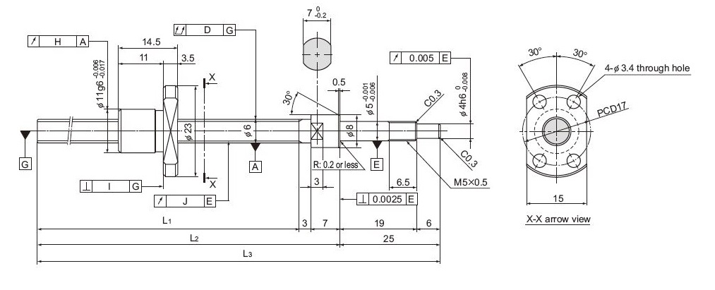
Model No. Stroke Screw shaft length Ball screw specifications Lead angle accuracy L1 L2 L3 Runout of the screw shaft axisD Runout of the nut circumferenceH Flange perpen-dicularityI Runout of the thread groove srufaceJ Representative travel distance error Fluctuation mm mm mm mm mm mm mm mm mm mm BNK0601‑3G0+100LC3Y 40 65 75 100 0.015 0.009 0.008 0.008 ±0.008 0.008 BNK0601‑3G0+100LC5Y 40 65 75 100 0.025 0.012 0.01 0.01 ±0.018 0.018 BNK0601‑3G0+130LC3Y 70 95 105 130 0.02 0.009 0.008 0.008 ±0.008 0.008 BNK0601‑3G0+130LC5Y 70 95 105 130 0.035 0.012 0.01 0.01 ±0.018 0.018 BNK0601‑3G0+160LC3Y 100 125 135 160 0.025 0.009 0.008 0.008 ±0.01 0.008 BNK0601‑3G0+160LC5Y 100 125 135 160 0.035 0.012 0.01 0.01 ±0.02 0.018 AFB-LF is the default grease. For more detailed specifications, please download the Product Catalog with the link in the Downloads section on this page. -
Ball screw specification Screw shaft diameter (mm) 8 Lead (mm) 1 BCD (mm) 8.2 Thread minor diameter (mm) 7.3 Number of circuits 3×1 Axial clearance 0 Basic dynamic load rating Ca (kN) 0.64 Basic static load rating C0a (kN) 1.4 Preload torque (N-m) to 0.018 Spacer ball None Rigidity (N/µm) 80 Circulation method Deflector Applicable fixed side support unit EK6, FK6 Applicable support side support unit EF6, FF6 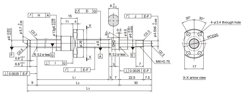
Model No. Stroke Screw shaft length Ball screw specifications Lead angle accuracy L1 L2 L3 Runout of the screw shaft axisD Runout of the nut circumferenceH Flange perpen-dicularityI Runout of the thread groove srufaceJ Representative travel distance error Fluctuation mm mm mm mm mm mm mm mm mm mm BNK0801‑3G0+115LC3Y 40 66 76 115 0.025 0.009 0.008 0.008 ±0.008 0.008 BNK0801‑3G0+115LC5Y 40 66 76 115 0.025 0.012 0.01 0.01 ±0.018 0.018 BNK0801‑3G0+145LC3Y 70 96 106 145 0.03 0.009 0.008 0.008 ±0.008 0.008 BNK0801‑3G0+145LC5Y 70 96 106 145 0.035 0.012 0.01 0.01 ±0.018 0.018 BNK0801‑3G0+175LC3Y 100 126 136 175 0.03 0.009 0.008 0.008 ±0.01 0.008 BNK0801‑3G0+175LC5Y 100 126 136 175 0.035 0.012 0.01 0.01 ±0.02 0.018 BNK0801‑3G0+225LC3Y 150 176 186 225 0.035 0.009 0.008 0.008 ±0.01 0.008 BNK0801‑3G0+225LC5Y 150 176 186 225 0.05 0.012 0.01 0.01 ±0.02 0.018 AFB-LF is the default grease. For more detailed specifications, please download the Product Catalog with the link in the Downloads section on this page. -
Ball screw specification Screw shaft diameter (mm) 8 Lead (mm) 2 BCD (mm) 8.3 Thread minor diameter (mm) 7 Number of circuits 3×1 Axial clearance 0 Basic dynamic load rating Ca (kN) 1.4 Basic static load rating C0a (kN) 2.3 Preload torque (N-m) to 0.02 Spacer ball None Rigidity (N/µm) 100 Circulation method Deflector Applicable fixed side support unit EK6, FK6 Applicable support side support unit EF6, FF6 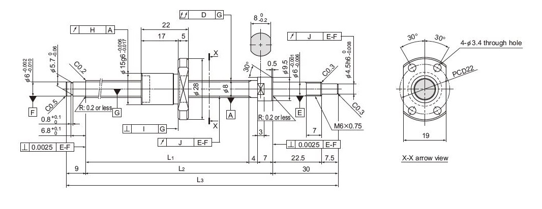
Model No. Stroke Screw shaft length Ball screw specifications Lead angle accuracy L1 L2 L3 Runout of the screw shaft axisD Runout of the nut circumferenceH Flange perpen-dicularityI Runout of the thread groove srufaceJ Representative travel distance error Fluctuation mm mm mm mm mm mm mm mm mm mm BNK0802‑3RRG0+125LC3Y 40 75 86 125 0.025 0.009 0.008 0.008 ±0.008 0.008 BNK0802‑3RRG0+125LC5Y 40 75 86 125 0.025 0.012 0.01 0.01 ±0.018 0.018 BNK0802‑3RRG0+155LC3Y 70 105 116 155 0.03 0.009 0.008 0.008 ±0.01 0.008 BNK0802‑3RRG0+155LC5Y 70 105 116 155 0.035 0.012 0.01 0.01 ±0.02 0.018 BNK0802‑3RRG0+185LC3Y 100 135 146 185 0.03 0.009 0.008 0.008 ±0.01 0.008 BNK0802‑3RRG0+185LC5Y 100 135 146 185 0.035 0.012 0.01 0.01 ±0.02 0.018 BNK0802‑3RRG0+235LC3Y 150 185 196 235 0.035 0.009 0.008 0.008 ±0.01 0.008 BNK0802‑3RRG0+235LC5Y 150 185 196 235 0.05 0.012 0.01 0.01 ±0.02 0.018 AFB-LF is the default grease. For more detailed specifications, please download the Product Catalog with the link in the Downloads section on this page. -
Ball screw specification Screw shaft diameter (mm) 10 Lead (mm) 2 BCD (mm) 10.3 Thread minor diameter (mm) 9 Number of circuits 3×1 Axial clearance 0 Basic dynamic load rating Ca (kN) 1.5 Basic static load rating C0a (kN) 2.9 Preload torque (N-m) to 0.025 Spacer ball None Rigidity (N/µm) 100 Circulation method Deflector Applicable fixed side support unit EK8, FK8 Applicable support side support unit EF8, FF6 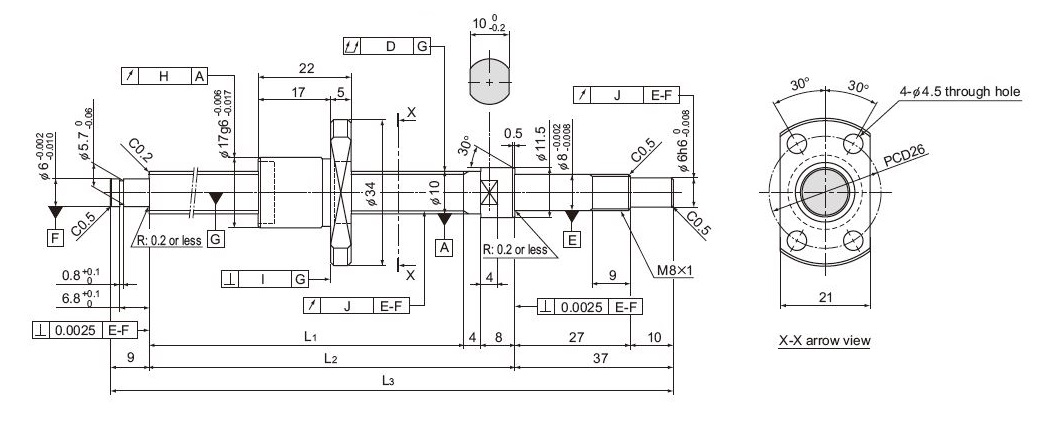
Model No. Stroke Screw shaft length Ball screw specifications Lead angle accuracy L1 L2 L3 Runout of the screw shaft axisD Runout of the nut circumferenceH Flange perpen-dicularityI Runout of the thread groove srufaceJ Representative travel distance error Fluctuation mm mm mm mm mm mm mm mm mm mm BNK1002‑3RRG0+143LC3Y 50 85 97 143 0.02 0.009 0.008 0.007 ±0.008 0.008 BNK1002‑3RRG0+143LC5Y 50 85 97 143 0.035 0.012 0.01 0.011 ±0.018 0.018 BNK1002‑3RRG0+193LC3Y 100 135 147 193 0.03 0.009 0.008 0.007 ±0.01 0.008 BNK1002‑3RRG0+193LC5Y 100 135 147 193 0.035 0.012 0.01 0.011 ±0.02 0.018 BNK1002‑3RRG0+243LC3Y 150 185 197 243 0.03 0.009 0.008 0.007 ±0.01 0.008 BNK1002‑3RRG0+243LC5Y 150 185 197 243 0.04 0.012 0.01 0.011 ±0.02 0.018 BNK1002‑3RRG0+293LC3Y 200 235 247 293 0.03 0.009 0.008 0.007 ±0.012 0.008 BNK1002‑3RRG0+293LC5Y 200 235 247 293 0.04 0.012 0.01 0.011 ±0.023 0.018 AFB-LF is the default grease. For more detailed specifications, please download the Product Catalog with the link in the Downloads section on this page. -
Ball screw specification Screw shaft diameter (mm) 10 Lead (mm) 4 BCD (mm) 10.5 Thread minor diameter (mm) 7.8 Number of circuits 1×2.5 Axial clearance 0 Basic dynamic load rating Ca (kN) 2.1 Basic static load rating C0a (kN) 2.7 Preload torque (N-m) 0.0098 to 0.042 Spacer ball 1:1 Rigidity (N/µm) 50 Circulation method Return Pipe Applicable fixed side support unit EK10, FK10 Applicable support side support unit EF10, FF10 Applicable nut bracket MC1004 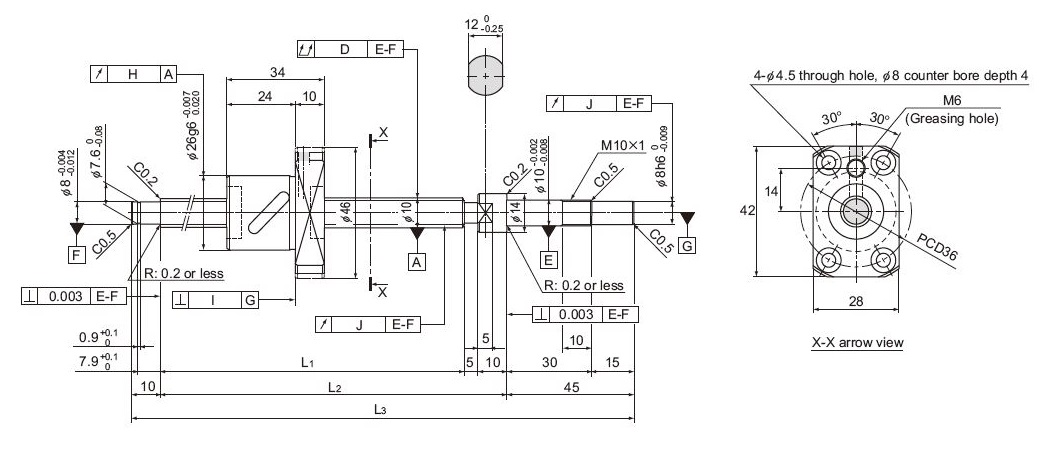
Model No. Stroke Screw shaft length Ball screw specifications Lead angle accuracy L1 L2 L3 Runout of the screw shaft axisD Runout of the nut circumferenceH Flange perpen-dicularityI Runout of the thread groove srufaceJ Representative travel distance error Fluctuation mm mm mm mm mm mm mm mm mm mm BNK1004‑2.5RRG0+180LC3Y 50 110 125 180 0.02 0.009 0.008 0.008 ±0.01 0.008 BNK1004‑2.5RRG0+230LC3Y 100 160 175 230 0.03 0.009 0.008 0.008 ±0.01 0.008 BNK1004‑2.5RRG0+280LC3Y 150 210 225 280 0.03 0.009 0.008 0.008 ±0.012 0.008 BNK1004‑2.5RRG0+330LC3Y 200 260 275 330 0.04 0.009 0.008 0.008 ±0.012 0.008 BNK1004‑2.5RRG0+380LC3Y 250 310 325 380 0.04 0.009 0.008 0.008 ±0.012 0.008 AFB-LF is the default grease. For more detailed specifications, please download the Product Catalog with the link in the Downloads section on this page. -
Ball screw specification Screw shaft diameter (mm) 10 Lead (mm) 10 BCD (mm) 10.5 Thread minor diameter (mm) 7.8 Number of circuits 1×1.5 Axial clearance 0 Basic dynamic load rating Ca (kN) 1.3 Basic static load rating C0a (kN) 1.6 Preload torque (N-m) 0.0098 to 0.049 Spacer ball 1.1 Rigidity (N/µm) 70 Circulation method Return Pipe Applicable fixed side support unit EK10, FK10 Applicable support side support unit EF10, FF10 Applicable nut bracket MC1004 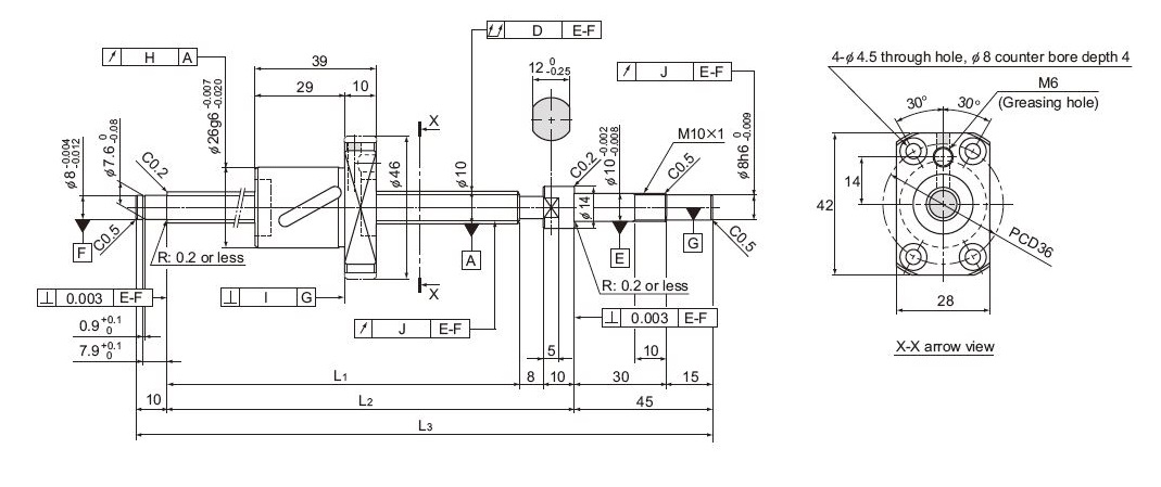
Model No. Stroke Screw shaft length Ball screw specifications Lead angle accuracy L1 L2 L3 Runout of the screw shaft axisD Runout of the nut circumferenceH Flange perpen-dicularityI Runout of the thread groove srufaceJ Representative travel distance error Fluctuation mm mm mm mm mm mm mm mm mm mm BNK1010‑1.5RRG0+240LC5Y 100 167 185 240 0.04 0.012 0.01 0.011 ±0.02 0.018 BNK1010‑1.5RRG0+290LC5Y 150 217 235 290 0.04 0.012 0.01 0.011 ±0.023 0.018 BNK1010‑1.5RRG0+340LC5Y 200 267 285 340 0.05 0.012 0.01 0.011 ±0.023 0.018 BNK1010‑1.5RRG0+390LC5Y 250 317 335 390 0.05 0.012 0.01 0.011 ±0.025 0.02 BNK1010‑1.5RRG0+440LC5Y 300 367 385 440 0.065 0.012 0.01 0.011 ±0.025 0.02 AFB-LF is the default grease. For more detailed specifications, please download the Product Catalog with the link in the Downloads section on this page. -
Ball screw specification Screw shaft diameter (mm) 12 Lead (mm) 2 BCD (mm) 12.3 Thread minor diameter (mm) 11 Number of circuits 3×1 Axial clearance 0 Basic dynamic load rating Ca (kN) 1.7 Basic static load rating C0a (kN) 3.6 Preload torque (N-m) 0.0040 to 0.034 Spacer ball None Rigidity (N/µm) 120 Circulation method Return Pipe Applicable fixed side support unit EK10, FK10 Applicable support side support unit EF10, FF10 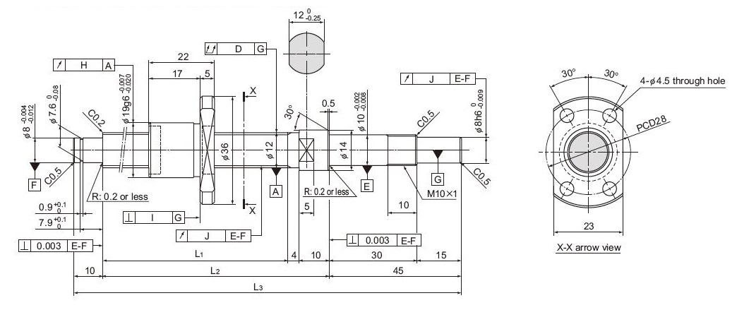
Model No. Stroke Screw shaft length Ball screw specifications Lead angle accuracy L1 L2 L3 Runout of the screw shaft axisD Runout of the nut circumferenceH Flange perpen-dicularityI Runout of the thread groove srufaceJ Representative travel distance error Fluctuation mm mm mm mm mm mm mm mm mm mm BNK1202‑3RRG0+154LC3Y 50 85 99 154 0.02 0.01 0.008 0.007 ±0.008 0.008 BNK1202‑3RRG0+154LC5Y 50 85 99 154 0.035 0.012 0.01 0.011 ±0.018 0.018 BNK1202‑3RRG0+204LC3Y 100 135 149 204 0.03 0.01 0.008 0.007 ±0.01 0.008 BNK1202‑3RRG0+204LC5Y 100 135 149 204 0.04 0.012 0.01 0.011 ±0.02 0.018 BNK1202‑3RRG0+254LC3Y 150 185 199 254 0.03 0.01 0.008 0.007 ±0.01 0.008 BNK1202‑3RRG0+254LC5Y 150 185 199 254 0.04 0.012 0.01 0.011 ±0.02 0.018 BNK1202‑3RRG0+304LC3Y 200 235 249 304 0.04 0.01 0.008 0.007 ±0.012 0.008 BNK1202‑3RRG0+304LC5Y 200 235 249 304 0.05 0.012 0.01 0.011 ±0.023 0.018 BNK1202‑3RRG0+354LC3Y 250 285 299 354 0.04 0.01 0.008 0.007 ±0.012 0.008 BNK1202‑3RRG0+354LC5Y 250 285 299 354 0.05 0.012 0.01 0.011 ±0.023 0.018 AFB-LF is the default grease. For more detailed specifications, please download the Product Catalog with the link in the Downloads section on this page. -
Ball screw specification Screw shaft diameter (mm) 12 Lead (mm) 5 BCD (mm) 13.3 Thread minor diameter (mm) 9.6 Number of circuits 1×2.5 Axial clearance 0 Basic dynamic load rating Ca (kN) 2.3 Basic static load rating C0a (kN) 3.7 Preload torque (N-m) 0.0040 to 0.034 Spacer ball None Rigidity (N/µm) 60 Circulation method Return Pipe Applicable fixed side support unit EK10, FK10 Applicable support side support unit EF10, FF10 Applicable nut bracket MC1205 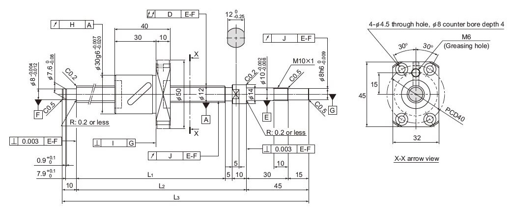
Model No. Stroke Screw shaft length Ball screw specifications Lead angle accuracy L1 L2 L3 Runout of the screw shaft axisD Runout of the nut circumferenceH Flange perpen-dicularityI Runout of the thread groove srufaceJ Representative travel distance error Fluctuation mm mm mm mm mm mm mm mm mm mm BNK1205‑2.5RRG0+180LC3Y 50 110 125 180 0.02 0.009 0.008 0.008 ±0.01 0.008 BNK1205‑2.5RRG0+180LC5Y 50 110 125 180 0.035 0.012 0.01 0.011 ±0.02 0.018 BNK1205‑2.5RRG0+230LC3Y 100 160 175 230 0.03 0.009 0.008 0.008 ±0.01 0.008 BNK1205‑2.5RRG0+280LC3Y 150 210 225 280 0.03 0.009 0.008 0.008 ±0.012 0.008 BNK1205‑2.5RRG0+280LC5Y 150 210 225 280 0.04 0.012 0.01 0.011 ±0.023 0.018 BNK1205‑2.5RRG0+330LC3Y 200 260 275 330 0.04 0.009 0.008 0.008 ±0.012 0.008 BNK1205‑2.5RRG0+330LC5Y 200 260 275 330 0.05 0.012 0.01 0.011 ±0.023 0.018 BNK1205‑2.5RRG0+380LC3Y 250 310 325 380 0.04 0.009 0.008 0.008 ±0.012 0.008 BNK1205‑2.5RRG0+380LC5Y 250 310 325 380 0.05 0.012 0.01 0.011 ±0.023 0.018 AFB-LF is the default grease. For more detailed specifications, please download the Product Catalog with the link in the Downloads section on this page. -
Ball screw specification Screw shaft diameter (mm) 14 Lead (mm) 2 BCD (mm) 14.3 Thread minor diameter (mm) 13 Number of circuits 3×1 Axial clearance 0 Basic dynamic load rating Ca (kN) 1.8 Basic static load rating C0a (kN) 4.3 Preload torque (N-m) 0.0049 to 0.049 Spacer ball None Rigidity (N/µm) 140 Circulation method Deflector Applicable fixed side support unit EK12, FK12 Applicable support side support unit EF12, FF12 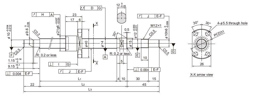
Model No. Stroke Screw shaft length Ball screw specifications Lead angle accuracy L1 L2 L3 Runout of the screw shaft axisD Runout of the nut circumferenceH Flange perpen-dicularityI Runout of the thread groove srufaceJ Representative travel distance error Fluctuation mm mm mm mm mm mm mm mm mm mm BNK1402‑3RRG0+166LC3Y 50 85 99 166 0.02 0.01 0.008 0.009 ±0.008 0.008 BNK1402‑3RRG0+166LC5Y 50 85 99 166 0.025 0.012 0.01 0.012 ±0.018 0.018 BNK1402‑3RRG0+216LC3Y 100 135 149 216 0.025 0.01 0.008 0.009 ±0.01 0.008 BNK1402‑3RRG0+216LC5Y 100 135 149 216 0.03 0.012 0.01 0.012 ±0.02 0.018 BNK1402‑3RRG0+266LC3Y 150 185 199 266 0.025 0.01 0.008 0.009 ±0.01 0.008 BNK1402‑3RRG0+266LC5Y 150 185 199 266 0.03 0.012 0.01 0.012 ±0.02 0.018 BNK1402‑3RRG0+316LC3Y 200 235 249 316 0.03 0.01 0.008 0.009 ±0.012 0.008 BNK1402‑3RRG0+316LC5Y 200 235 249 316 0.04 0.012 0.01 0.012 ±0.023 0.018 BNK1402‑3RRG0+416LC3Y 300 335 349 416 0.04 0.01 0.008 0.009 ±0.013 0.01 BNK1402‑3RRG0+416LC5Y 300 335 349 416 0.05 0.012 0.01 0.012 ±0.025 0.02 AFB-LF is the default grease. For more detailed specifications, please download the Product Catalog with the link in the Downloads section on this page. -
Ball screw specification Screw shaft diameter (mm) 14 Lead (mm) 4 BCD (mm) 14.65 Thread minor diameter (mm) 12.2 Number of circuits 3×1 Axial clearance 0 Basic dynamic load rating Ca (kN) 4.2 Basic static load rating C0a (kN) 7.6 Preload torque (N-m) 0.0098 to 0.069 Spacer ball None Rigidity (N/µm) 190 Circulation method Deflector Applicable fixed side support unit EK12, FK12 Applicable support side support unit EF12, FF12 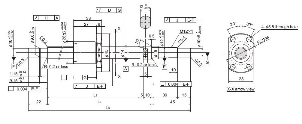
Model No. Stroke Screw shaft length Ball screw specifications Lead angle accuracy L1 L2 L3 Runout of the screw shaft axisD Runout of the nut circumferenceH Flange perpen-dicularityI Runout of the thread groove srufaceJ Representative travel distance error Fluctuation mm mm mm mm mm mm mm mm mm mm BNK1404‑3RRG0+230LC3Y 100 148 163 230 0.025 0.01 0.008 0.009 ±0.01 0.008 BNK1404‑3RRG0+230LC5Y 100 148 163 230 0.03 0.012 0.01 0.012 ±0.02 0.018 BNK1404‑3RRG0+280LC3Y 150 198 213 280 0.025 0.01 0.008 0.009 ±0.01 0.008 BNK1404‑3RRG0+280LC5Y 150 198 213 280 0.03 0.012 0.01 0.012 ±0.02 0.018 BNK1404‑3RRG0+330LC3Y 200 248 263 330 0.03 0.01 0.008 0.009 ±0.012 0.008 BNK1404‑3RRG0+330LC5Y 200 248 263 330 0.04 0.012 0.01 0.012 ±0.023 0.018 BNK1404‑3RRG0+430LC3Y 300 348 363 430 0.04 0.01 0.008 0.009 ±0.013 0.01 BNK1404‑3RRG0+430LC5Y 300 348 363 430 0.05 0.012 0.01 0.012 ±0.025 0.02 BNK1404‑3RRG0+530LC3Y 400 448 463 530 0.045 0.01 0.008 0.009 ±0.015 0.01 BNK1404‑3RRG0+530LC5Y 400 448 463 530 0.055 0.012 0.01 0.012 ±0.027 0.02 AFB-LF is the default grease. For more detailed specifications, please download the Product Catalog with the link in the Downloads section on this page. -
Ball screw specification Screw shaft diameter (mm) 14 Lead (mm) 8 BCD (mm) 14.75 Thread minor diameter (mm) 11.2 Number of circuits 1×2.5 Axial clearance 0 Basic dynamic load rating Ca (kN) 4.3 Basic static load rating C0a (kN) 5.8 Preload torque (N-m) 0.02 to 0.078 Spacer ball 1:1 Rigidity (N/µm) 80 Circulation method Return Pipe Applicable fixed side support unit EK12, FK12 Applicable support side support unit EF12, FF12 Applicable nut bracket MC1408 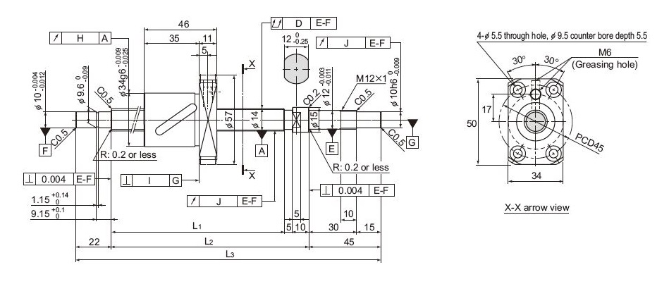
Model No. Stroke Screw shaft length Ball screw specifications Lead angle accuracy L1 L2 L3 Runout of the screw shaft axisD Runout of the nut circumferenceH Flange perpen-dicularityI Runout of the thread groove srufaceJ Representative travel distance error Fluctuation mm mm mm mm mm mm mm mm mm mm BNK1408‑2.5RRG0+321LC5Y 150 239 254 321 0.035 0.015 0.011 0.012 ±0.023 0.018 BNK1408‑2.5RRG0+371LC5Y 200 289 304 371 0.035 0.015 0.011 0.012 ±0.023 0.018 BNK1408‑2.5RRG0+421LC5Y 250 339 354 421 0.04 0.015 0.011 0.012 ±0.025 0.02 BNK1408‑2.5RRG0+471LC5Y 300 389 404 471 0.04 0.015 0.011 0.012 ±0.025 0.02 BNK1408‑2.5RRG0+521LC5Y 350 439 454 521 0.04 0.015 0.011 0.012 ±0.027 0.02 BNK1408‑2.5RRG0+571LC5Y 400 489 504 571 0.04 0.015 0.011 0.012 ±0.027 0.02 BNK1408‑2.5RRG0+621LC5Y 450 539 554 621 0.04 0.015 0.011 0.012 ±0.03 0.023 BNK1408‑2.5RRG0+671LC5Y 500 589 604 671 0.04 0.015 0.011 0.012 ±0.03 0.023 BNK1408‑2.5RRG0+721LC5Y 550 639 654 721 0.065 0.015 0.011 0.012 ±0.035 0.025 BNK1408‑2.5RRG0+771LC5Y 600 689 704 771 0.065 0.015 0.011 0.012 ±0.035 0.025 BNK1408‑2.5RRG0+871LC5Y 700 789 804 871 0.085 0.015 0.011 0.012 ±0.035 0.025 AFB-LF is the default grease. For more detailed specifications, please download the Product Catalog with the link in the Downloads section on this page.
| Model | Screw shaft outer diameter | Lead(in mm) | No. of circuits*1 | Seals | Clearance | Shaft length(in mm)*1 | Accuracy | Standard stock symbol | ||
| BNK | 04 | 01 | - | 3 | G0 | + | 77L | C3 | Y | |
| BNK | 04 | 01 | Various | No symbol : No seal | G0 : 0 | Length in millimeters then "L" | C3 | Y | ||
| 05 | 02 | RR : Labyrinth seal | ||||||||
| 06 | 04 | |||||||||
| 08 | 05 | |||||||||
| 10 | 08 | |||||||||
| 12 | 10 | |||||||||
| 14 |