ES
Slider Type
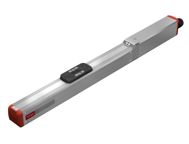
Slider Type of Stepper Motor Actuator
Hide Filters
Show Filters
Shopping Options
Please Log-in to see pricing, CAD Models and Catalogs
Don't have an account? Sign up here.
In stock
Related Products


-
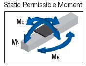
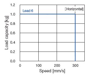
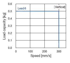
Control device type TSC Motor □28 Ball screw lead [mm] 6 Max load weight [kg] Acceleration and deceleration rate Horizontal 0.3G 1 Vertical 0.2G 0.5 Running life1 [km] 5000 Positioning repeatability [mm] ±0.020 Lost motion [mm] 0.1 Static permissible moment2 [N-m] MA:6.0, MB:7.5, MC:5.9 1. Service life is based on below conditions. Conditions: Horizontal or vertical, under the maximum load capacity, overhang length A=6mm, B and C=0mm, 0.3G for horizontal, 0.2G for vertical, stroke 50mm
2. Maximum permissible moment when unit is stationary. Applied point of moment load for MA and MC are the top face of the table, and that for MB is the center of the table.

Stroke [mm]
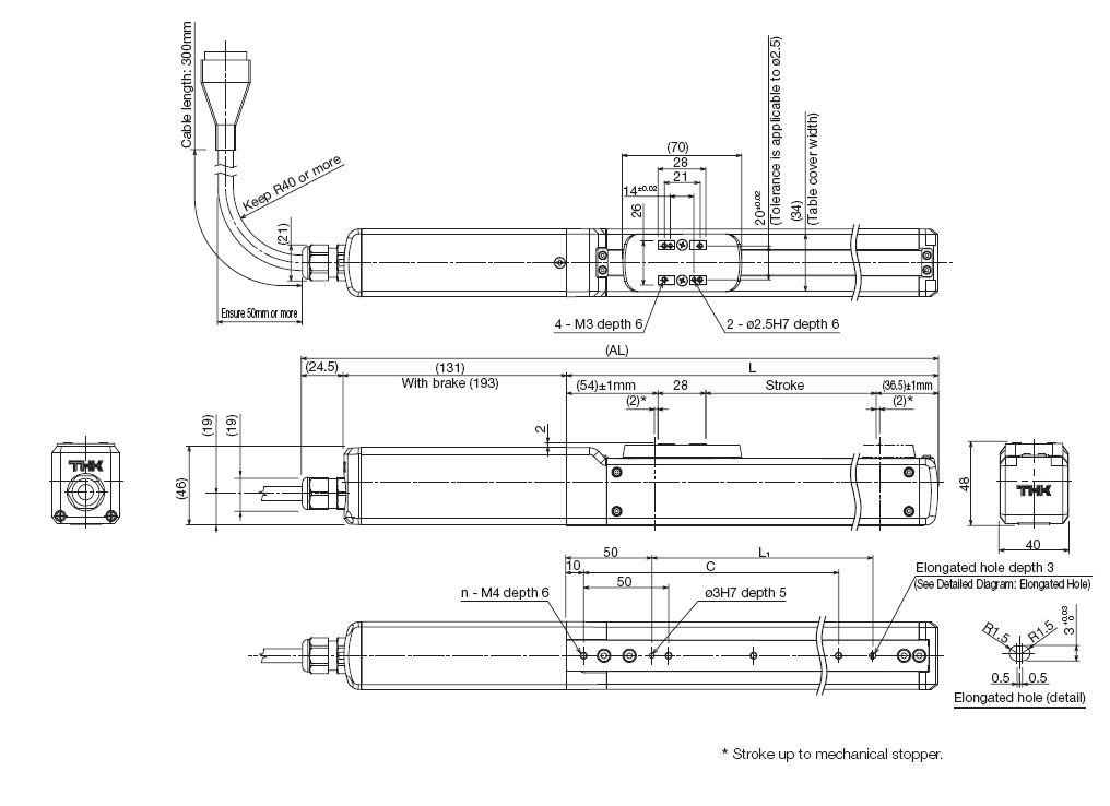
(Stroke between mechanical stoppers)Maximum speed [mm/s] Ball screw lead: 6mm 300 Dimensions [mm] AL 320 370 420 470 520 570 L 160.2 210.2 260.2 310.2 360.2 410.2 L1 85 135 185 235 285 335 C 100 150 200 250 300 350 Mounting hole count n 3 4 5 6 7 8 Weight [kg] 1.0 1.0 1.1 1.1 1.3 1.3 AFF is the default grease. For more detailed specifications, please download the catalog with the link at the top of the page -
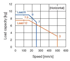
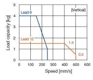
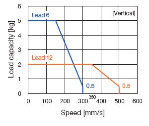
Control device type TSC Motor □35 Ball screw lead [mm] 6 12 Max load weight [kg] Acceleration and deceleration rate Horizontal 0.3G 9 7.5 Vertical 0.2G 4 1.5 Running life1 [km] 5000 Positioning repeatability [mm] ±0.020 Lost motion [mm] 0.1 Static permissible moment2 [N-m] MA:9.3, MB:13.5, MC:17.7 1. Service life is based on below conditions. Conditions: Horizontal or vertical, under the maximum load capacity, overhang length A=6mm, B and C=0mm, 0.3G for horizontal, 0.2G for vertical, stroke 50mm
2. Maximum permissible moment when unit is stationary. Applied point of moment load for MA and MC are the top face of the table, and that for MB is the center of the table.
Stroke [mm]
(Stroke between mechanical stoppers)Maximum speed [mm/s] Ball screw lead: 6mm 250 x 250 x 250 x 250 x Ball screw lead: 12mm x 500 x 500 x 500 x 500 Dimensions [mm] AL 324 374 424 474 524 574 624 674 L 168.5 218.5 268.5 318.5 368.5 418.5 468.5 518.5 L1 80 130 180 230 280 330 380 430 C 100 150 200 250 300 350 400 450 Mounting hole count n 3 4 5 6 7 8 9 10 Weight [kg] 1.5 1.6 1.7 1.8 1.9 2.0 2.1 2.2 AFF is the default grease. For more detailed specifications, please download the catalog with the link at the top of the page -
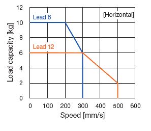
Control device type TSC Motor □42 Ball screw lead [mm] 6 12 Max load weight [kg] Acceleration and deceleration rate Horizontal 0.3G 10 6 Vertical 0.2G 5 2 Running life1 [km] 5000 Positioning repeatability [mm] ±0.020 Lost motion [mm] 0.1 Static permissible moment2 [N-m] MA:10.5, MB:22, MC:22.1 1. Service life is based on below conditions. Conditions: Horizontal or vertical, under the maximum load capacity, overhang length A=6mm, B and C=0mm, 0.3G for horizontal, 0.2G for vertical, stroke 50mm
2. Maximum permissible moment when unit is stationary. Applied point of moment load for MA and MC are the top face of the table, and that for MB is the center of the table.
Stroke [mm]
(Stroke between mechanical stoppers)Maximum speed [mm/s] Ball screw lead: 6mm 300 x 300 x 300 x 300 x 300 x Ball screw lead: 12mm x 500 x 500 x 500 x 500 x 500 Dimensions [mm] AL 330 380 430 480 530 580 630 680 730 780 L 170.5 220.5 270.5 320.5 370.5 420.5 470.5 520.5 570.5 620.5 L1 90 140 190 240 290 340 390 440 490 540 L2 100 50 100 50 100 50 100 50 100 50 C 0 100 100 200 200 300 300 400 400 500 Mounting hole count n 2 3 3 4 4 5 5 6 6 7 Weight [kg] 2.1 2.2 2.3 2.5 2.6 2.8 2.9 3.0 3.2 3.3 AFF is the default grease. For more detailed specifications, please download the catalog with the link at the top of the page -
Control device type TSC Motor □42 Ball screw lead [mm] 6 12 Max load weight [kg] Acceleration and deceleration rate Horizontal 0.3G 10 6 Vertical 0.2G 5 2 Running life1 [km] 5000 Positioning repeatability [mm] ±0.020 Lost motion [mm] 0.1 Static permissible moment2 [N-m] MA:10.5, MB:22, MC:22.1 1. Service life is based on below conditions. Conditions: Horizontal or vertical, under the maximum load capacity, overhang length A=6mm, B and C=0mm, 0.3G for horizontal, 0.2G for vertical, stroke 50mm
2. Maximum permissible moment when unit is stationary. Applied point of moment load for MA and MC are the top face of the table, and that for MB is the center of the table.
Stroke [mm]
(Stroke between mechanical stoppers)Maximum speed [mm/s] Ball screw lead: 6mm 300 x 300 x 300 x 300 x 300 x 270 230 Ball screw lead: 12mm x 500 x 500 x 500 x 500 x 500 x 460 Dimensions [mm] AL 336 386 436 486 536 586 636 686 736 786 836 886 L 176.5 226.5 276.5 326.5 376.5 426.5 476.5 526.5 576.5 626.5 676.5 726.5 L1 90 140 190 240 290 340 390 440 290 340 390 440 C 0 100 100 200 200 300 300 400 400 500 500 600 Mounting hole count n 2 3 3 4 4 5 5 6 6 7 7 8 Weight [kg] 2.4 2.6 2.7 2.8 3.0 3.1 3.3 3.4 3.5 3.7 3.8 4.0 AFF is the default grease. For more detailed specifications, please download the catalog with the link at the top of the page
| Model | Size | Ball screw lead | Stroke | Design symbol | Control device type | Options | Motor used | Home position | Cable length | |||||||
| ES | 3 | - | 06 | - | 0050 | B | - | TS | / | 28P | - | D00 | - | S3 | ||
| ES | 3 | 06: 6mm | 0050: 50mm | B | TS: TSC | No symbol: None | 28P: ⬜28 | D00: Motor side | S3: 3m | |||||||
| 4 | 12: 12mm | 0100: 100mm | ||||||||||||||
| 5 | 0150: 150mm | |||||||||||||||
| 0200: 200mm | ||||||||||||||||
| 0250: 250mm | ||||||||||||||||
| 0300: 300mm | ||||||||||||||||
| 0350: 350mm | ||||||||||||||||
| 0400: 400mm | ||||||||||||||||
| 0450: 450mm | ||||||||||||||||
| 0500: 500mm | ||||||||||||||||
| 0550: 550mm | ||||||||||||||||
| 0600: 600mm | ||||||||||||||||